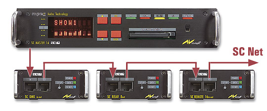
The SC Net System is a network consisting of an SC Master unit and one or several SC Net modules for controlling a variety of devices. All SCNet modules are run via one single bidirectional connection, which also serves as a power supply.
See also
SC Master units
Addresses for SC Net operation
All components are run via one single network connection made of standard Cat5 cable with a length of up to 1,000 m. Usually, the modules are connected in series. With a distributor module, however, the arrangement of cables can also be star shaped. The compact dimensions of these modules permit them to be located next to the devices to be controlled, which means that this is the location where the numerous connecting cables are branched off and can therefore be kept very short.
Unused SC Net outputs must be terminated. In large, widely branched networks, you should use modules with Iso-PlugIns for potential isolation and optimum operating safety. See Iso PlugIn.
 When an application is to be exclusively run from a PC with Wings Vioso RX, SC Net modules can be directly connected to a serial port on your PC. See Direct PC operation of SC Net modules.
SC Net modules are supplied via the SC Master or additional power supply units and the network line. The power supplied additionally is not only available for the module connected to the power supply unit, but for all SC Net modules within the network. Usually, the power supply unit AC-3 can supply up to five SC Net modules. However, there are also some modules which require a separate power supply unit.
Device address 1 is always allocated to the master unit. Device addresses 2 to 125 are used for the modules (slaves) within the network. If address 2 or higher is allocated to an SC Master unit, it is regarded as a module within the network.
Every SC Net device offers particular functions to be addressed via sub addresses. When SC Net devices were added to the Media Pool under Devices, they are always displayed with their corresponding functions, with Wings Vioso RX automatically providing for the addressing. Addressing, however, can be changed at any time. An SC RELAY 8out, for instance, would be visible as 8 switching contacts with addresses 2/1 to 2/8, i.e. 2 would be the device address and 1 to 8 the sub addresses of the individual relay contacts.
SC Master units, too have a number of interfaces addressable via subaddresses. See SC Net subaddresses of SC Master units.
To change addresses, for example, when using modified hardware for controlling, proceed as follows:
Click the plus sign next to category  Devices in the Media Pool and highlight the corresponding SC Net port below it. Following this the devices are listed on the right.
Right-click the corresponding control channel and select Properties. The Properties Dialog will appear.
Under Address enter the new address and confirm with OK.
For an SC Net Module to be able to perform the programmed functions requires the device address as it is listed in the Media Pool under Devices to be set in the module. Currently the address setting is performed via SC Master components. At a later time, this will also be possible via Wings Vioso RX.
This is how you set the device addresses at the SC Master and the SC Net Modules:
Connect the SC Master with the SC Net Modules and switch it on.
In the SC Master menu go to Options – SC-Net – NetAdrs and select NA=1.
In order to establish communication within the SC Net, switch on the SC Master and off again. When starting up the SC Master, a message such as "SC-Baud: 460800" must briefly be displayed, with the value depending on the baud rate negotiated. After communication has been established, the blue SC NET LED at the SC Net modules will blink at an interval of a few seconds. In the event of no communication being established, refer to Ensuring communication within the SC Net for more information.
Under Options – SC-Net – ExtAdrs select the address you want to allocate to an SC Net Module, e.g. EA=2.
By pressing Enter at the SC Master, all connected SD Net modules are set to configuration mode. This is indicated by the DATA LEDs blinking while the SC Master sends the address into the network. Both remain active for 20 seconds.
During this time, press the SETUP button of the SC Net Module to be configured to save the address. You may have to use a pen to press the setup button. This terminates configuration mode.
You can now check the address set for the module. If you press the Setup button, the module address is briefly displayed on the Master unit display. If this does not work for your units, you may have to update the operating software.
If a show is programmed via a DLC port, e.g. via an SD EC 2X4, because slide projectors need to be controlled as well, only the lower SC Net addresses must be used. A DLC port allows 32 switches, 32 RS232 channels and 32 analog channels to be used for the same DLC address, as the information is saved as separate commands in every address. An exception are DMX channels, which contain identical information on the first 32 channels, i.e. they are arranged in parallel, just like analog channels.
Some configuration examples :
32 relays, to be implemented via four SC RELAY 8out units:
1st Module, device address 2, 8 switching outputs with the DLC addresses A1 to D2
2nd Module, device address 3, 8 switching outputs with the DLC addresses A3 to D4
3rd Module, device address 4, 8 switching outputs with the DLC addresses A5 to D6
4th Module, device address 5, 8 switching outputs with the DLC addresses A7 to D8
32 OC switches to be implemented via two SC OPEN COLLECTOR 16out components:
1st Module, device address 2, 16 switching outputs with the DLC addresses A1 to D4
2nd Module, device address 3, 16 switching outputs with the DLC addresses A5 to D8
8 relays via SC RELAY 8out and
16 OC switches via SC OPEN COLLECTOR 16out:
1st Module, device address 2, 8 switching outputs with the DLC addresses A1 to D2
2nd Module, device address 3, 16 switching outputs with the DLC addresses A5 to D8
16 OC switches via one SC OPEN COLLECTOR 16out,
16 channels 0 – 10 Volts via two SC ANALOG 8out and
4 channels RS 232 via one SC SERIAL 4in-out:
1st Module, device address 2, 16 switching outputs with the DLC addresses A1 to D4
2nd Module, device address 2, 8 channels 0 – 10 Volts with the DLC addresses A1 to D2
3rd Module, device address 3, 8 channels 0 – 10 Volts with the DLC addresses A3 to D4
4th Module, device address 2, 4 serial outputs with the DLC addresses A1 to D1
16 channels 0 – 10 Volts via two SC ANALOG 8out and
16 channels DMX via one SC DMX in-out:
1st Module, device address 2, 8 channels 0 – 10 Volts with the DLC addresses A1 to D2
2nd Module, device address 3, 8 channels 0 – 10 Volts with the DLC addresses A3 to D4
3rd Module, device address 2, 64 DMX channels with the DLC addresses A1 to D8
Although the SC DMX in-out can output 128 channels, only 32 analog/DMX channel can be programmed for a DLC port. As the first 16 0 – 10 Volt channels are used in our example, or the same information is output as DMX, respectively, only DLC addresses starting from A5 can be used for DMX control in this case.